The objective of this installation guide is to assist technicians in installing the Denowatts hardware in under a couple of hours (most sites) with a single trip. Please read these tips and guidelines to ensure long-term benchmarking success, especially items required before heading to the project site.
Please contact Denowatts at any point with questions, 978.309.6688 x1 or support@denowatts.com
Bring with you:
- The Denowatts kit (typical equipment and installation materials are included)
- Step Ladder (tall enough to reach the top of a solar module)
- Bubble level (if installing a horizontal Deno sensor)
- A technician qualified to perform 24Vdc work in the DAS cabinet
Inspect Kits
Kits are ordered based on project-specific benchmarking requirements. The equipment consists of Gateway and Deno kits.
Gateway Kit:
- Gateway
- Power Cable (1m) with DC Barrel connector
- Antenna Assembly
- (1) antenna
- Mounting Hardware (pole mount: 2 bolts and bracket)
- 15' Coaxial Cable
- Cable gland
- Surge Protector
- Ethernet Cable (1m)
Deno Kit
- Deno Sensor, Bracket, and (2) C-clamps
- Antenna Assembly
- (1 or 2) Antennas (fixed-tilt POA kit vs tracker POA kit)
- Mounting Hardware (Panel Mount: Angled bracket, Bolt and 2" washer)
- 15' coaxial cable
- (TBOM) Back of Module Temperature sensor (6' lead)
- Alcohol prep pad and drying cloth
- A spare piece of recloseable fastener
- Wire management clips
- OPTIONAL - rPOA - auxiliary pyranometer for bifacial modules
- OPTIONAL - GHI - auxiliary pyranometer for horizontal mount with double ball joint mounting arm
- OPTIONAL - 3rd party pyranometer
Download Mobile App
Denowatts provides a free mobile application available both on the Apple store and Google Play app store. Use the link below or search "Denowatts" in the appropriate app store.
Placement
Locating and orienting Deno sensors within the project site is critical to a successful installation. Improperly located or mounted sensors will require correction, possibly by a second site visit. If your design team has not yet provided a location plan, please consult with them first. Denowatts can assist with this process.
If your engineering team cannot provide sensor location information, please look at the PV array drawings and civil plan sets to get a basic idea of the site layout and where to place the hardware. Deno sensors should be located in the sunniest parts of the array, with at most a 1/4 mile line of sight to the Gateway antenna. Larger sites using more than one Deno sensor should distribute them to representative locations. For tracker sites, ensure Deno sensors are located on independent rows.
When determining a location, start thinking about the following:
1. Equipment Pad Locations
- is the gateway (s) in a central point for radio transmissions from the sensor(s)
2. Antenna Considerations
- Are the Gateway and Deno sensor antennas within 1200 feet line-of-sight? Obstructions between antennas, such as other solar modules, chain link fences, and roofing, substantially reduce the effective transmission distance.
- If on tracker site, are you using dual antennas for trackers to ensure at least one antenna is always located above the upper plane of the array
3. Site Size, shape, and terrain
- How many different solar planes are there? How many Denos are included?
- Is this a tracker or fixed tilt system?
- Where are the sunniest locations on the array? Are there any shading impacts that should be avoided?
Please contact support@denowatts.com (978.309.6688 x1) for consultation/questions about sensor placement.
Please also see our full support article on the proper location of Deno Sensors in the array: "How to Pick a Deno Sensor Location"
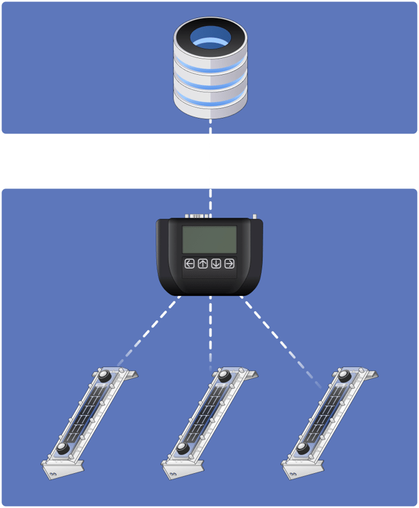
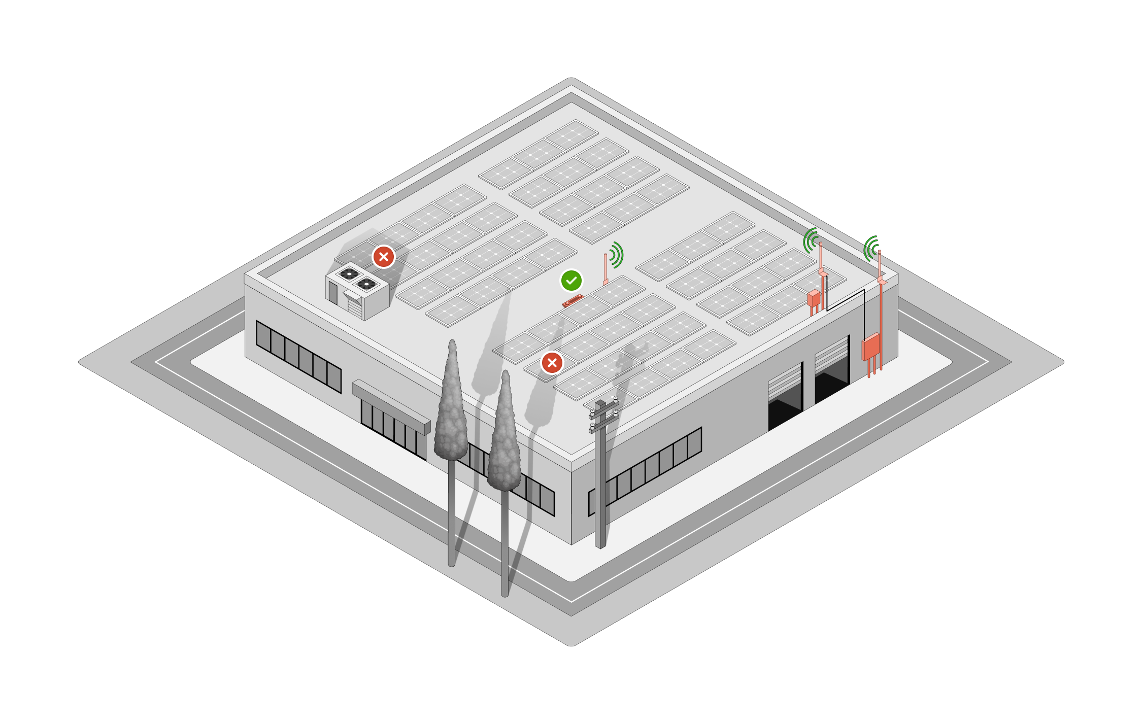
Example:
Single-axis tracker with two Deno sensors. The Denowatts Gateway is placed on a nearby equipment pad in the weatherproof DAS enclosure. Denos are placed on distributed tracker rows, avoiding shading from obstructions like trees and other equipment. The antennas maintain a line of sight throughout the day, and the gateway antenna is mounted vertically as high up as possible on a piece of unistrut.
-png.png)
For the first business onsite we will want to get these Deno sensors charged up. Deno sensors are self-powered but will not operate fresh out of the box. The Denos must be charged to complete installation and verification. There are two charging options:
- Place in direct moderate sunlight for an hour.
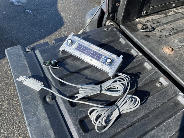
OR
- Charge via USB cable from any power source.
With the mobile app in hand and the pre-site checklist complete, the first installation step is to install the Gateway, including power and internet.
Gateway Introduction
The Denowatts Gateway is a receiver/coordinator for all Deno sensors. It serves as both a Modbus server, providing data to 3rd party monitoring applications, as well as a Modbus client, acquiring data directly from local devices. As the Deno sensor hub, data is received, processed, and transmitted to cloud servers.
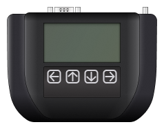
The diagram above shows the front face of the Denowatts Gateway. Note the LCD screen and push button interface. The back face includes a DIN rail mounting clip.
-png.png?width=463&height=148&name=Marketing%2c%20Gateway%20back%203%20(2)-png.png)
The diagram above shows the top face of the gateway. Note the following connection ports from left to right:
-
- Threaded Antenna Port (RP-SMA)
- USB Type B
- USB Type A
- Ethernet Port
- Serial Comm Port
- 12-24V barrel jack power input
- Power status lights
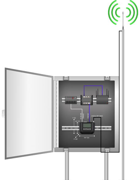
The Gateway must be installed in a waterproof (NEM4) enclosure, typically the main DAS cabinet. The Gateway requires:
-
- 12-24Vdc power supply (the Gateway draws ~2watts)
- Internet access (LAN via RJ45 cable)
Once you have found a suitable enclosure: (with adequate space and power supply)
- Mount the Gateway on available DIN rail space.
- Use provided barrel jack power cable and connect the 12-24Vdc power source with the enclosure
- verify green power status light is on (immediate)
- The LCD screen may take up to 30 seconds to display
- Install the ethernet cable that connects the Gateway to a network switch within the enclosure
-
- Verify ethernet status lights are operating
Gateway Installation:
Gateway Antenna Mounting
Now that the Gateway is securely mounted and connected to the DAS, the next step is installing its antenna. The antenna is essential in the Denowatts system because the sensors communicate to the Gateway via radio frequency (900Mhz zigbee protocol). The antenna enables this communication process.When installing the antenna, please consider the following:
- Read the full "Denowatts Antenna Placement" Article. But to sum it up:
- The antenna must be placed outside the DAS enclosure.
- High up as possible (usually mounted on piece of unistrut 8-10 feet off ground)
- Vertical Orientation - very important for how the magnetic fields work.
- Line-of-sight with Deno Sensors (or where sensors will be. In most cases, there is more flexibility in deno sensor placement than gateway placement)
- The antenna must be installed a minimum of 4-6 feet away from other antennas on the equipment pad.
- Cellular Antennas
- Tracker Communication Antennas
- Tracker GPS antennas
- The antenna cable must be run through the bottom of the DAS enclosure through a waterproof cable gland. (do not make any new cut-outs in the top or side of the enclosure, be sure to check your DAS OEM equipment warranty details).
- Connect the antenna to Gateway with a finger-tight connection.
-png.png)
Here are a few examples of antenna installations:
Roof Top:
Notice how the gateway antenna is installed on the roof and not on the side of the building to create a line of sight between the antennas. All antennas are also mounted in a vertical orientation.
-png.png)
Option A: An antenna with an extender cable can be run up the side of the building to the rooftopto create a line-of-sight between the antennas.
Option B: Deno Gateway antenna is extended up the side of the building, mounted horizontally, 3' off the wall, and the Deno Sensor antenna is brought to the edge of the building to create a line-of-sight with the Deno gateway antenna.
Option C: The Gateway can be mounted in a NEMA4 enclosure on the rooftop to create a line-of-sight between antennas.
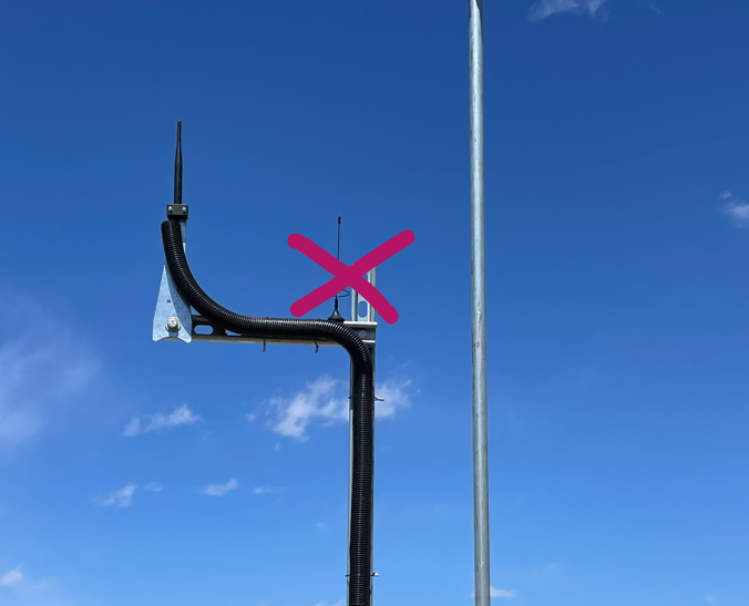
**If the antenna is too close to other antennas at the pad, communication problems will ensue. Little adjustments can make a big difference.**
**It is important that the antenna is mounted a foot away from any wall or poll**
This is an example of an antenna that is too close to another antenna:
Tracker:
Notice how the gateway antenna is installed high up on a pole to allow the line of sight into a tracking array. Notice how there are two antennas for each POA sensor, and that one antenna is mounted on each edge of the tracking table.
-png-1.png)
Fixed Tilt:
Notice how the gateway antenna is installed high up on a pole to allow the line of sight into a tracking array. Notice how the Deno antennas are installed far enough away from the sensor to avoid shading on the sensor.
![]()
2D Sectional of Ground Mounts:
Notice how antennas are installed on the top edge of the panel to create the best line of site with Gateway
-png.png)
Network Settings
Typically a static IP must be set to enable communication with the internet or for 3rd party data acquisition. The owner will define the desired IP.
Use the Denowatts mobile APP or the push pad on the gateway to adjust the network settings:
- Mobile App: See recording in the Verification section
- Gateway Push pad:
The Gateway is installed, its antenna is mounted high, and you have verified that the Gateway is reaching the internet. Note: Even if the Gateway is not connected to the internet, Deno communication can still be using the Gateway LCD screen.
1. Make sure the Deno sensors are charged up.
-
- Place the sensor in direct moderate-full strength sunlight for about an hour
- Place the sensor in direct moderate-full strength sunlight for about an hour
-
- If dark, charge the sensor for 15 minutes via another power source using USB port/cable (like the gateway USB port)
- If dark, charge the sensor for 15 minutes via another power source using USB port/cable (like the gateway USB port)
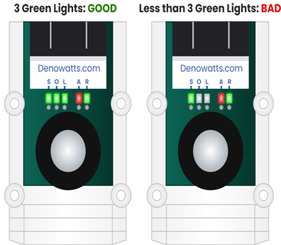
There is no “ON” switch for the Deno sensors. When suitably powered, they will immediately begin reporting to the nearest Gateway. To immediately see if a Deno sensor is powered, swipe the reset switch using a magnet and observe the S-O-L LEDs monetarily flash. If they do not flash, the Deno is not yet charged.
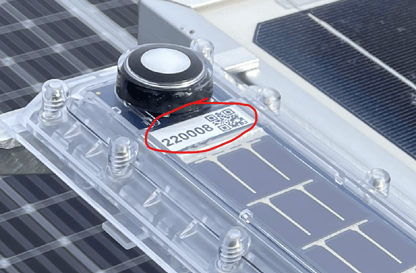
With the Deno sensors within 20 feet of the Gateway, view the Mobile App or check the Gateway LCD to view the Deno sensor data by serial number. When placed in direct sunlight, the Deno sensors will report records every minute.
-png.png?width=253&height=235&name=2%20(6)-png.png)
Data timestamps will show up in the app and gateway with the Deno serial number, which is located underneath the top pyranometer, shown below:
Mobile App Communication Check:
Gateway LCD Screen Check:
Note: If dark, the Deno sensors may be placed into Launch Mode using a magnet. Hold a strong magnet over the top side of the Deno sensor, as shown below, until the S-O-L LEDs all illuminate green. This indicates that the Deno is in Launch Mode. Every 15 seconds the A-R LEDs will flash, indicating that a record has been reported. If all S-O-L lights remain illuminated, the transmission is a success. If S-O-L lights disappear, the transmissions are not reaching the Gateway, and troubleshooting steps are required. The Launch Mode will automatically stop after 10 minutes.
Use magnet over top pyranometer to initiate LAUNCH MODE:
-png.png?width=191&height=289&name=3%20(1)-png.png)
2. Verify communication from each Deno.
Noting the serial number on the front of each Deno sensor, ensure records from each device using the Mobile App or the Gateway LCD. Also, check the sensor records to ensure irradiance and temperature report valid readings.
Move Deno sensors to their final mounting locations as defined by the engineering team. If no location has been specified, please review our Guide to Locating Deno Sensors.
**TIP: Before mounting any Deno sensors, please check that communication is operational at their final mounting locations using the previous steps. This prevents unnecessary sensor shuttling and re-mounting.**
Plane of Array (POA) Deno Sensor Installation
- Mount the Deno Sensor to the side or top of a module, as shown below per the module mounting type (tracker vs fixed tilt).
- Mount the antenna, ensuring line of sight with the Gateway antenna.
**NOTE: See Antenna Installation Article; Antennas should be vertical orientation, continuous line-of-sight, 4-6 away from other antennas, within 1200 feet**
**NOTE: Do not shade the Deno sensor with the antenna**
**Tip: Even if you can’t see the Gateway antenna, as long as there are no obstructions between them, the Deno sensor will communicate reliably over ¼ mile.** - Verify that the Deno sensor data is reporting reliably using the Mobile App or Gateway LCD, including valid readings for the irradiance and temperature.
- Mount the Back-of-Module Temperature sensor (Tbom) and any Auxillary Pyranometers (rPOA or GHI). Since these sensors are adhered to, this step should be completed.
- Tbom - 24" from module frame, must not be on a module on the perimeter of an array for a more representative sample.
- RPOA - 15' in from the end of the row. Must not be on first or last row of modules for a more representative sample
- Tidy up loose wires with zip ties, wire clips, and/or sun-bundlers. Ensure wires are secure to the module and away from moving tracker parts, sharp edges, DC cables,
- Finally, use the Mobile App to document the complete Deno sensor, including BOM temperature and auxiliary pyranometers, with photos and a location description. Following the App’s instructions, take pictures of each Deno sensor's front, back, antenna line-of-sight, auxiliary sensor mounts, and wire management. These photos are automatically uploaded to the Denowatts project folder.
**Tip: Verify and document each Deno Sensor before proceeding to the next**
Module Mounting Type
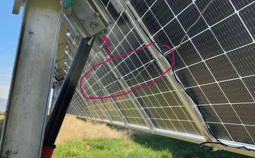
Single Axis Tracker
Towards the center axis of the panel, close to the torque tube.
**Must not be on the first or last row of the tracker table.**
-jpg-1.jpeg?width=572&height=517&name=4%20(1)-jpg-1.jpeg)
![]()
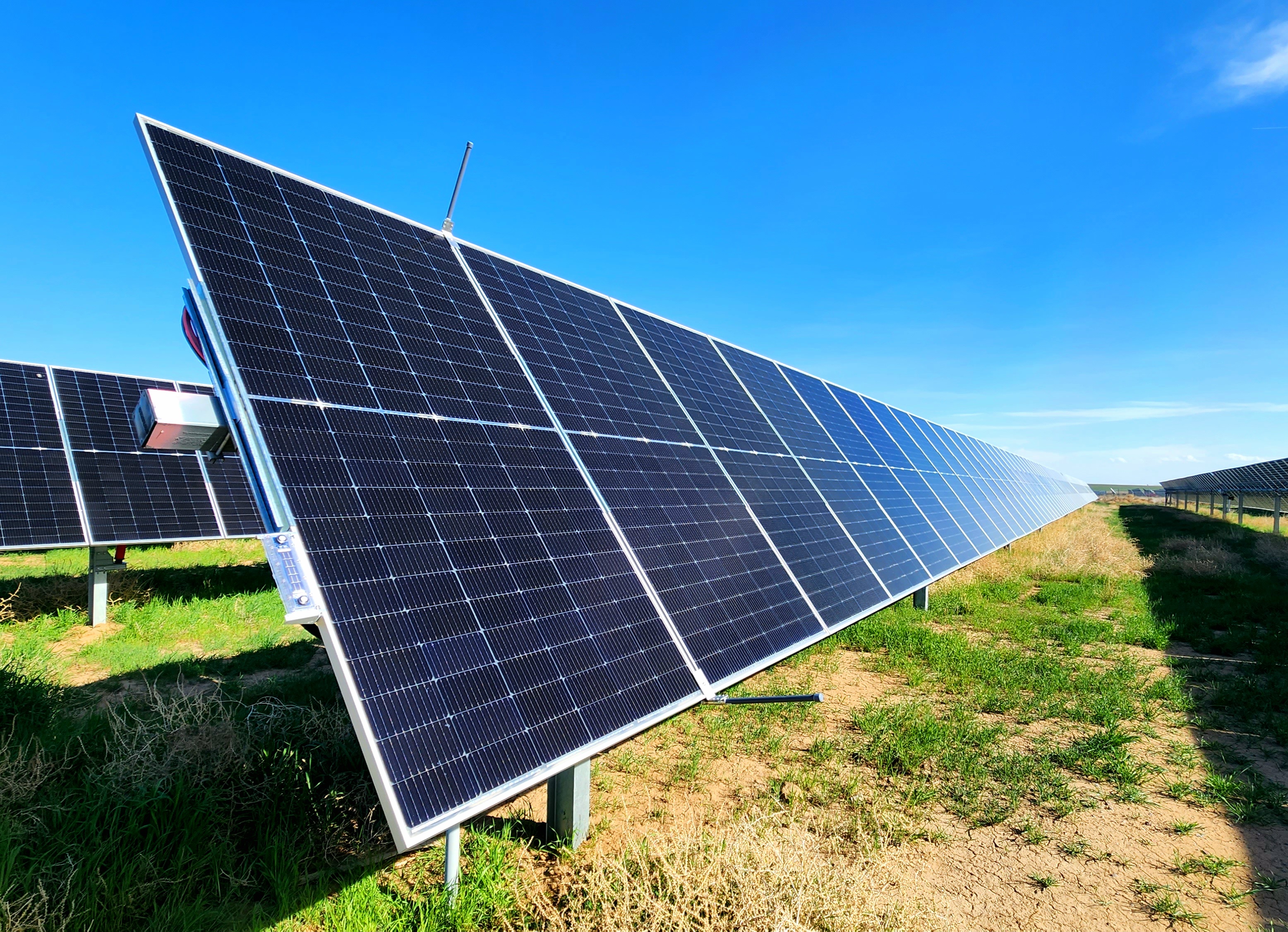
Fixed Tilt Ground Mount
On the top edge of the panel frame or as high up on the panel side edge as possible
-png-1.png?width=802&height=504&name=Marketing%2c%20Deno%20on%20solar%20panel%20color%2c%20gradient%20(4)-png-1.png)
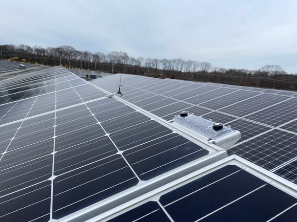
Fixed Tilt Roof Mount
On the top edge of the module frame or as high up on the panel edge as possible, just like in the previous image.
Carport
On the top edge of the module frame or as high up on the panel edge as possible, just like in the previous image.
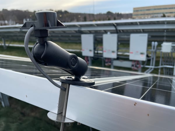
Horizontal Deno Installation (Optional)
In some cases, orders may have specified one or more Deno sensors to be mounted in the horizontal position rather than the Plane of Array. Deno sensors are mounted horizontally using a ball arm bracket mounted at the top of solar modules in a location unobstructed by shade.
- Attach the ball arm bracket to solar module frame using the supplied 1/4-20 machine screws, wingnuts, and washers.
- Verify horizontal position to <1 degree using an installer-supplied level.
Caution: Do not mount Deno Sensor anywhere near poles, trees, or other taller equipment.
-png.png)
Sensor Antenna Mounting
Please read the "Deno Antenna Placement" article for complete antenna installation details. The most important thing to remember when it comes to mounting the antenna for the Deno Sensor:
**Must be continuous a line-of-site with Gateway Antenna, no more than 1200 feet apart, and 4-6 feet away from other antennas**
Please take a look below at where the antenna is installed. For a fixed tilt system, it is as high up on the panel edge as it can be. To be sure not to shade the Deno sensor with the antenna, mount the antenna 10 feet from the Deno sensor.
For a tracker system: your kit should come with two antennas per POA Deno sensor. One antenna should be mounted on each edge of the table to ensure line-of-sight throughout the day as the array angle changes (shown below).
- Screw the antenna into the back of the Deno sensor.
- Use the hardware included in the kit to mount the antenna between two modules on the high edge of the array. Tighten into place.
- Tidy up any remaining cable with zip ties and wire clips away from DC cables and moving tracker parts
-png-1.png?width=1304&height=369&name=Antenna%20Setup%20Ground%20Mount%20(8)-png-1.png)
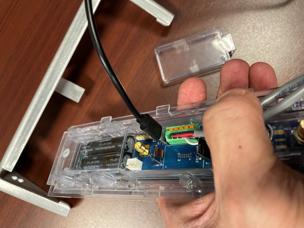
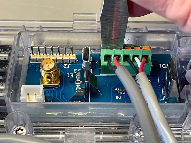
Auxiliary Sensors
Auxiliary sensors are plugged into the back of the Deno sensor. Ensure that the sensor wires are terminated properly in the terminal block on the back of the Deno sensor.
For Deno Models 4.0 and 4.1, confirm the following wire scheme:
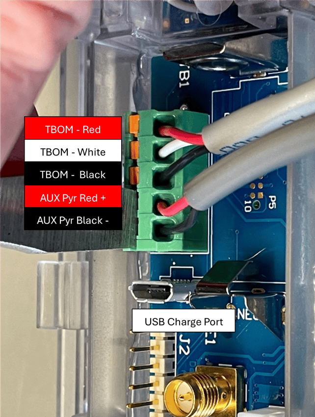
For Deno Models 4.2 and above, confirm the following wire scheme:
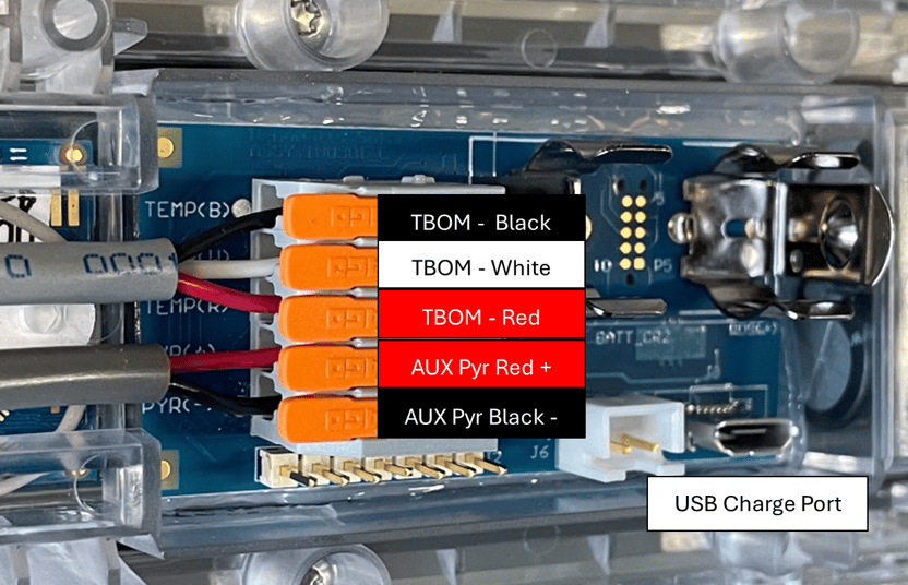
Tbom: Back of Module Temperature Sensor
Locate the Back of the Module Temperature Sensor (Tbom) approximately 24" from the edge of the panel on the back of the module. Ensure the sensor is not on a module at the end of a row and that the tip of the sensor is placed in the middle of a PV cell.
Ensure Tbom is not on an edge module of the array. (Avoid putting Tbom on perimeter panels)
-
- First lean the Tbom location with an alcohol pad and then completely dry it with a cloth
- Apply dual lock to the back of the panel
- Fasten Tbom mechanism via mating dual lock
- Ensure the sensor tip is secure against the panel
- Tidy up any remaining cable with zip ties and wire clips away from DC cables and moving tracker parts
-png-1.png)
Example Back of Module Temperature Sensor (TBOM) Installation:
Video of Installation:
rPOA: Rear Plane of Array Pyranometer
Locate the rear side irradiance Sensor (rPOA): 15 feet from the end of a row and not on the first or last row of the array. rPOAs cannot be installed on perimeter panels.
Tracker - 15 feet from the end of the row, not on the array's first or last row. Mount the sensor on the bottom of the torque tube.
Fixed Tilt - 15' feet from the end of the row, not on the array's first or last row. Mount the sensor 2/3's up from the bottom of the array.
-
- Clean the rPOA location with an alcohol pad and then completely dry it with a cloth
- Apply dual lock
- Fasten Tbom mechanism via mating dual lock
- Tidy up any remaining cable with zip ties and wire clips away from DC cables and moving tracker parts
**rPOA sensors should not be mounted on the first or last row of the tracker table and should be at least 15 feet from the end of a row**
Fixed Tilt rPOA and Tbom mounting location on the module:
-
- TBom equidistance from module frame and racking frame, not on an edge panel of array.
- rPOA is mounted 2/3rd of way up from bottom of array, and at least 15 feet from end of row. Not on arrays first or last row.
-png.png?width=793&height=710&name=1%20(1)-png.png)
%20(4)-png.png?width=533&height=603&name=Bifacial%20Modules%20(Fixed%20Tilt)%20(4)-png.png)
Example rPOA on Fixed Tilt System:
.jpeg?width=655&height=856&name=rPOA%20(Fixed%20Tilt).jpeg)
Tracking rPOA and Tbom mounting location on module:
- TBom equidistance from module frame and racking frame, not end of tracking table.
- rPOA is mounted on the bottom of the torque tube (if surface is parallel to backplane)
- or rPOA is mounted 1/3rd way down panel edge, avoiding torque tube shading. (if you cannot mount on the torque tube)
![]()
Example installation of rPOA on a tracking system:
Video of Installation:
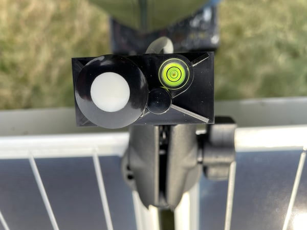
Auxiliary Horizontal Pyranometer
The Auxiliary GHI sensor is not the same as a GHI Deno Sensor. An Auxiliary GHI sensor connects to a POA Deno Sensor.
The Auxiliary GHI sensor comes plugged into the back of the Deno sensor and is mounted on a double ball joint mechanism for easy leveling on any surface mount.
-
- Use supplied hardware to mount the ball joint arm to the top edge of the array
- Adjust the ball joint arm so the bubble level on the pyranometer is in the center of the circle
- Tighten the knob of the ball joint arm to secure it in place
3rd Party Pyranometers
Another optional auxiliary sensor is the 3rd party pyranometer. This is not a part of the Denowatts kit and is supplied by the customer. To connect a 3rd party pyranometer:
- Follow 3rd party mounting installation instructions
- Terminate wires from the pyranometer onto the back of the Deno Sensor.
-png.png?width=518&height=318&name=Deno%20with%203rd%20Party%20Pyranometer%20(1)-png.png)
Wire Management
It is important to ensure that all extra wiring from the Deno antennas and auxiliary sensors are neatly tucked & secured. As well as:
- Away from any moving parts on a tracking system
- Away from DC home runs and cabling to prevent "noise"
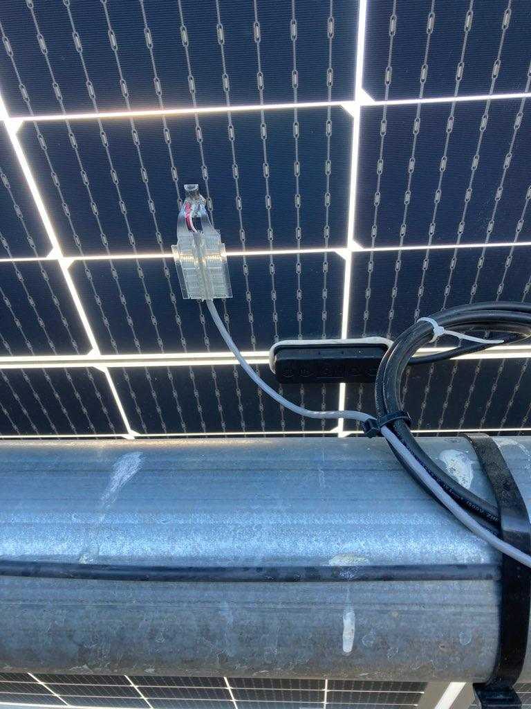
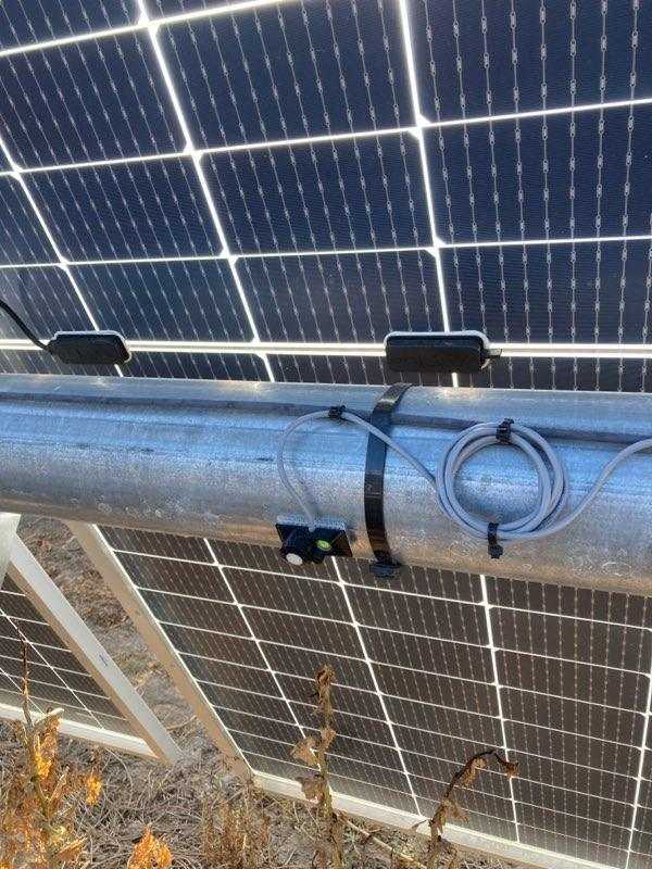
Here is an example of proper wire management for a Deno Sensor installation:
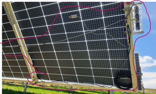
Here is an example of wire management to avoid moving tracker parts and DC cabling: